Use the placement drawing, A4 slab templates, or the custom printable sheet. The drawing is schematic; only the PDF and custom sheet are intended to print at physical scale.
What is dimensioned, and what is proposed
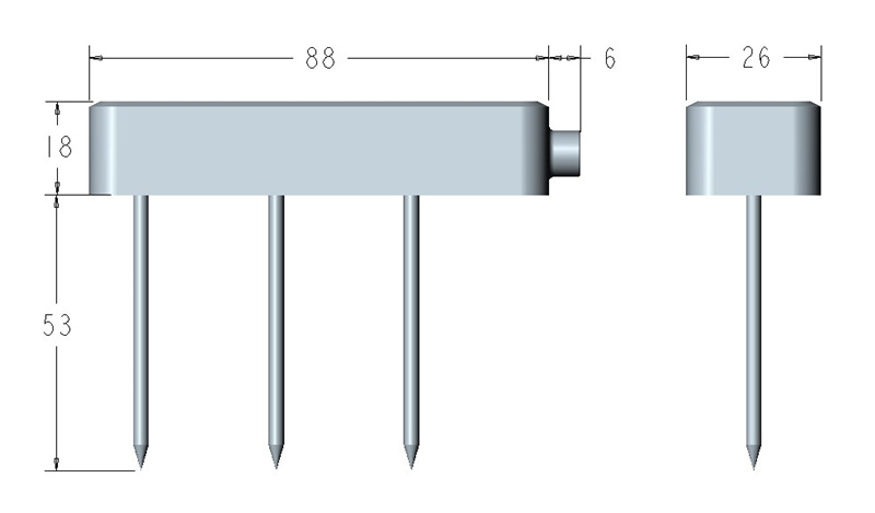
INFWIN's MT22 dimension drawing shows an 88 × 26 mm contact face, 18 mm housing depth and 53 mm rods. Compare these with your actual hardware revision. The published drawing does not dimension the distance between pins. The template deliberately has no guessed pin holes.
The midpoint positions below are project suggestions for a repeatable initial comparison, not manufacturer-validated MT22 positions for Grodan Prestige or every coco container. Mid-height is not mathematically guaranteed to represent mean water content. The sensing field extends around the electrodes; fully inserting the metal alone does not prove that the surrounding field is free of boundaries.
Cubes on a slab / slab only
- Confirm roots have entered the slab. Use the slab probe as the main measurement; keep a second cube probe if you need upper-block information. Record the move because the old cube trace and new slab trace cannot be treated as one continuous calibration.
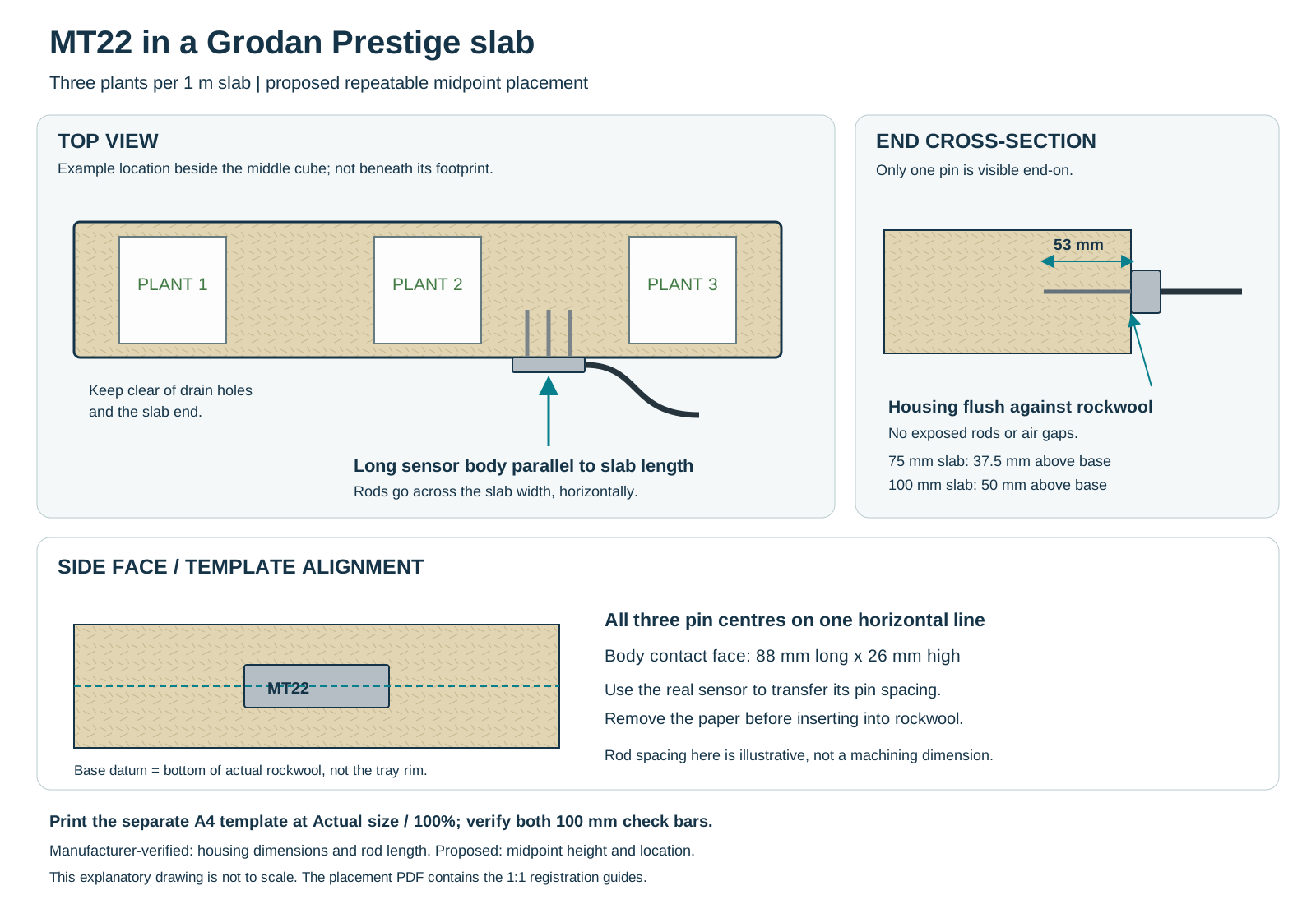
- Pick a representative slab. On a three-plant slab, start beside the middle block, outside its footprint, clear of slab ends and drain cuts. Record the actual distance from a slab end and the cube edge. Grodan's own GroSens placement instructions are for a different sensor; do not copy its bracket dimensions as MT22 dimensions.
- Enter through a long side. Hold the 88 mm body dimension horizontally along the slab length. The three rods point straight across the slab width and sit at the same elevation. Do not rotate the long body vertically in a shallow slab.
- A proposed starting rod centreline is 37.5 mm above the substrate base for a 75 mm slab, or 50 mm for a 100 mm slab. Measure from the bottom of the actual growing medium, not the gutter lip or wrapper seam. Check alternative positions against independent measurements before standardising a production layout.
- Pierce the wrapper only enough for the sensor. Insert all 53 mm of each rod without rocking, twisting, pre-drilling cavities or crushing the medium. The contact face should meet the substrate surface, with no air gap around the rods. Avoid touching a trough, support, neighbouring block or metal fitting with the sensing region.
- Support the cable so it cannot rotate the probe. Record location, orientation, depth, sensor serial, substrate lot and drain position. Calibrate in this geometry.
The factory does not publish an MT22/Prestige-specific minimum distance from every edge or dripper. Keep away from direct feed paths and test representativeness rather than presenting an invented exact offset as validated.
Cubes alone
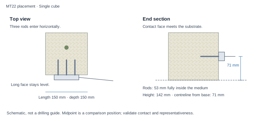
Use a repeatable side insertion into a sufficiently large block, with the rod row level. A midpoint height is an initial mapping position, subject to the same boundary and representativeness checks. A 150 mm-wide Hugo can accommodate the 88 mm contact face geometrically; that is not proof of whole-block accuracy.
Small propagation blocks need a different sensor or validation arrangement. A 75 mm-wide cube cannot accommodate the MT22's 88 mm-wide face in this orientation. Do not cut a larger hole or leave an outer pin in air. Some 100 mm blocks also leave very little lateral clearance; check the sensing footprint rather than relying solely on rod length. A physically smaller substrate-specific probe may be a better fit.
Coco / peat containers
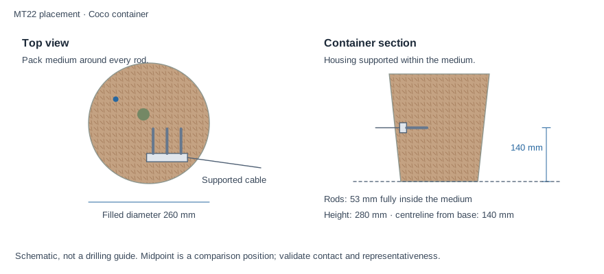
Measure at a recorded depth in the actual packed, rooted medium, away from the emitter stream, stem, drainage layer and container boundary. Map more than one depth or compare representative pots before choosing a standard position. The middle of the filled height is a possible initial comparison point, not a universal coco rule.
Where practical, place the sensor during filling and pack hydrated medium around all rods consistently without creating cavities or compacting a special dense pocket. On an established container, make a minimal side opening if the container design allows it and avoid repeated insertion through roots. A curved pot wall does not provide a flat 88 mm contact surface; verify full substrate contact along every rod instead of forcing the housing against the wall. Keep the chosen position fixed as moisture changes; coco shrinkage can create air gaps.
Different pot heights and media mixes need their own calibration and placement record. A probe in one container does not measure every container on its irrigation line.
Print and use the template
- The fixed slab PDF uses A4. The calculator generates A4 or US Letter sheets for your selected dimensions and units. Print Actual size / 100%, with Fit, Shrink and browser headers/footers disabled.
- Measure both perpendicular check bars: 100 mm in metric or 4 in in imperial. Aim for no more than 0.5 mm (0.02 in) discrepancy; reject a scaled print.
- Select the correct slab-height page. Align the base datum with the bottom of the medium. For a custom sheet marked Tall container, first mark the chosen height with a ruler and align its centreline; that sheet has no base datum.
- Transfer your actual sensor's three pin positions onto the printed centreline using scrap backing. Remove the paper before final insertion; do not drill oversized holes in the substrate.
- The printed 88 × 26 mm outline locates the housing. It does not calibrate VWC or prove the chosen location is representative.
If only one probe is available, establish a repeatable location and compare its trace with weighed samples, delivered volume and drainage. A second fixed probe or a load-cell reference can distinguish a local wet/dry pocket from a change across the whole root zone. These checks are more useful than forcing different positions to display the same number.